Tag Archives: distortion

Tire Ripples

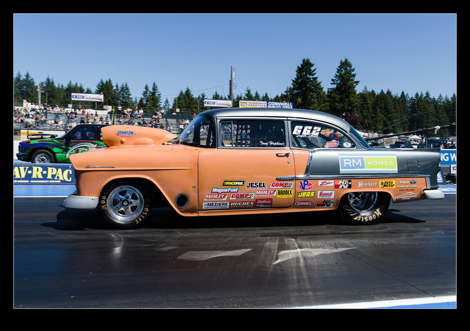
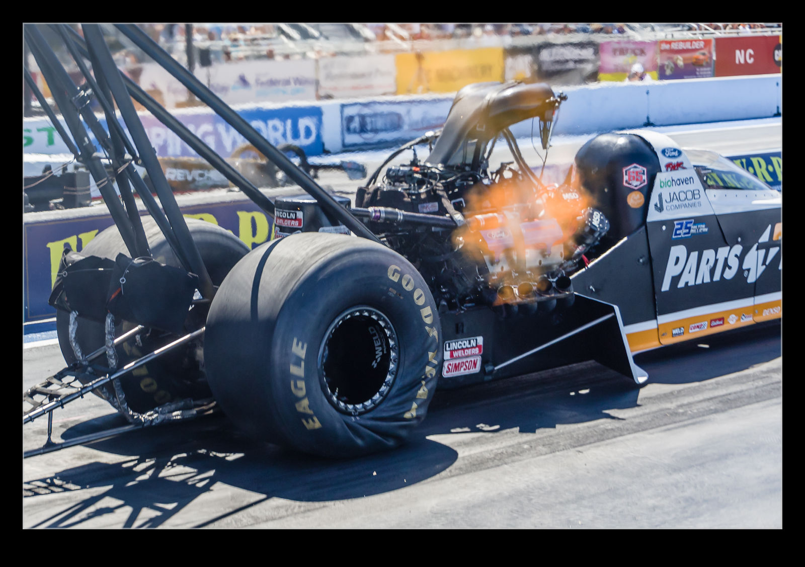
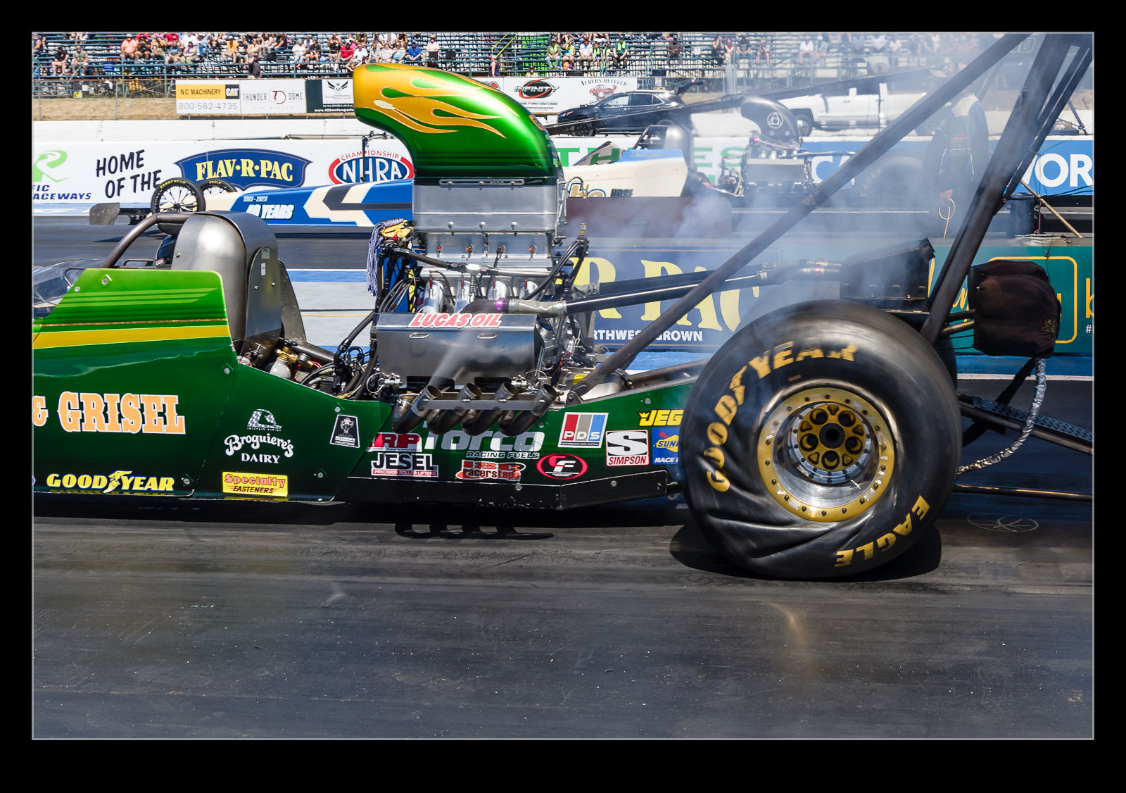
I had seen images from drag racing which showed how the tires get distorted as the immense amounts of torque are transferred through them.  A tire is at its most effective when it isn’t sliding but is in static contact with the ground.  You might recognize this from your own experience.  If you push something across a surface, the resistance reduces once the item starts moving.  The same thing happens with tires.  To get the best out of them spinning is not good.  With the tire gripping the surface but the axle rotating, the sidewall is the area that has to compensate which it does by distorting and then unloading as it drives the vehicle forwards.  I wanted to try and catch this so took a bunch of shots focused on trying to catch this moment.

Building A Cathedral On Boggy Ground

Winchester Cathedral was not built on the best of ground.  About 100 years ago, a major effort was made to save sections of the building from collapsing.  A diver spent many months under water in the pilings beneath the building bringing in material to shore everything up.  The effort was ultimately a success and some buttresses were added to take care of the rest.  However, this all was done after the walls had made some significant movement.  Today, this is still apparent when you look at some of the angles and realize that things are pointing in odd direction.  The original stone masons were not inaccurate.  Things just moved after they were done.  Their choice of foundations was more of the issue!

Diffraction Problems with Window Screens

Occasionally I will get aircraft heading in to Boeing Field come right by the house.  Late Friday afternoon, two Boeing test jets were coming my way.  One was the first 777X and the other was that first 737 Max7.  The usual route brings them just slightly north of the house so I was ready.  However, the Max was heading just slightly south of the normal track and looked like it might go the other side of the house.  At the last minute, I realized it would and ran through the the other side.

I got the window open but didn’t have time to remove the screen.  I thought it would take out some light but figured the large aperture of a big lens would just blur out the screen mesh since it was so close.  Through the viewfinder, things look pretty good.  However, when I downloaded the shots, I realized the shots were totally awful.  The screens had caused shadowing of the images.  The center image was there but I could see shadow versions about and below.  Then I got to one with a beacon flashing and that showed exactly how the pattern of light was scattered.  Based on what I see, I assume this is a diffraction effect.  It is a useless shot but it is very interesting which is why I am sharing it.

Creating Lens Profiles for Adobe Software

UPDATE:  It turns out, the upload process for the profile sends to an address that doesn’t work.  While I try to fix this, if you want the profiles to use, you can download them by clicking here.

Within Adobe processing software, there is lens correction functionality built in to the Lightroom Develop module (or Adobe Camera Raw in Photoshop) that compensates for distortion and vignetting in the lens the image was taken with.  Adobe has created a large number of lens profiles but they never created one for the Canon 500mm in its initial version.  Adobe also has an online tool for sharing profiles but this does not include one for this lens either.  The 600mm had a profile and it was supposedly close so I had been using that for a while.  Recently, though, I was shooting with the 1.4x teleconverter fitted and this introduced some new effects which required some manual tweaking to offset.

I still wasn’t happy with the result so I decided it was time to bite the bullet and create some profiles from scratch.  Adobe has a tool for creating a lens profile.  It involves printing out some grid targets which you then shoot a number of times to cover the whole of the frame.  It then calculates the profile.  I was shooting at both 500mm and 700mm so I needed a few targets.  To make a complete profile it is a good idea to shoot at a variety of focusing distances and with a range of apertures.  The tool comes with many targets.  Some I could print at home but some of the larger ones I got printed at FedEx and mounted on foam core to make them more rigid.  Then it was time to shoot a bunch of very boring shots.

The software is not the most intuitive I have ever worked with but it eventually was clear what I had to do.  (Why do some manual writers seem like they have never used the process they are writing about?)  I found out how to run the analysis for different charts and distances separately and append the data to the profile as I go.  I did need to quit the program periodically because it would run out of memory which seems like an odd bug these days.  After much processing and some dropped frames as a result of poor shooting on my part (even on the tripod I got some blur occasionally with very slow shutter speeds) it got a profile out.  The proof of the pudding is in the eating of course (that is what the actual phrase is for those of you that never get past the pudding part) so I tried the profile out on some recent shots.  It works!  I was rather delighted.  I may shoot a few more samples in good conditions to finish things off but this was a rather happy outcome.  Once I have tweaked the profiles sufficiently, I shall upload them to Adobe and anyone can use them.

Fisheye Correction in Lightroom

I have a pretty well defined routine for importing and processing my images in Adobe Lightroom. I have presets for importing images that put them in the right folders, apply copyright information and apply development presets. I can then edit from there as I go. One of the settings I have set as a default is the application of the lens correction settings. This setting deals with any natural vignette in the lens as well as some distortion. Occasionally this can be tricky if you have something close to the edge of a wide lens and it gets slightly chopped by the correction.

AU0E3419-2.jpg AU0E3419.jpgI discovered a more extreme version of this while processing some shots from the Lick Observatory. I had taken my 8-15mm fisheye zoom with me as I thought there might be some use for it in the telescope buildings. It turned out to be a good thing to have. When I first had the lens, Adobe had not created a profile for the lens so the shots came in uncorrected with the fisheye look I expected. More recently, Adobe have created a profile for this lens. It was added in one of the updates and, since I don’t use the lens all of the time, I hadn’t noticed.

AU0E3382-2.jpg AU0E3382.jpgWhen I was going through the shots, I noticed the wide shots had some strange distortion at the edges. I was perplexed by this and also wondered where the circular fisheye shots were because I was sure I had taken some. Only then did I realize that these were those shots and the corrections were being applied. Here are some examples of the before and after with the correction to give you a idea of what the transformation is. A pretty dramatic change. I might make use of this sometimes but I shall also have to remember switching this off when shots with this lens are involved.

Ripples in the Skin

AU0E4290.jpgThe construction technique for aluminum aircraft fuselages is known as semi-monocoque. A monocoque structure takes the entire load through the shell of the structure. In airframes, the skin is very thin and so frames and longerons are joined to the inside to provide additional rigidity while the skin still takes a lot of the load. If you haven’t ever seen the cross section of an aircraft structure, you may be surprised to see just how thin the skin panels actually are. They are perfectly up to the task of pressurization and bending loads so no need to panic.

AU0E4488.jpgAn outcome of this design approach is that the panels between the frames and longerons can experience some load directions that induce a measure of buckling. Nothing that is beyond their elastic limits but something that can be apparent if the light comes from the right angle. The lower side of the rear fuselage of the Boeing 757 is an area that is susceptible to this in certain flight conditions. I saw a number of them recently – both -200 and -300 models – and they both were showing visible distortion of the panels. The sun angle meant that the shadowing of these areas was apparent.

AU0E9169.jpgThe 757 is by no means the only aircraft to experience this phenomenon. The B-52 Superfortresss is a jet that shows this effect on plenty of occasions. I have heard people comment on it being a function of the age of the airframes but it is more of a result of the design of the basic structure than anything else. Certainly nothing to be immediately concerned about.

Update on the 100-400

Nearly a year ago I got the new model of the Canon 100-400 EF lens.  I had it on back order when it first came out and it arrived just before Christmas so became an impromptu gift to me!  Almost everything about the lens I liked.  However, if you read my initial thoughts on the lens which I covered here, you will have seen I had a concern about softness in one part of the image.  I have used the lens extensively since then and, while I have not always had an issue, I have continued to be concerned about the output in one area – particularly when compared the the excellent sharpness the rest of the image was displaying.

I sent the lens to Canon earlier this year for a service.  I explained my concerns and they took a look and told me it was functioning properly and returned it.  I took it on another shoot and got more shots which did not look right.  This time I emailed CPS and provided them with some sample shots.  They suggested it didn’t look right and told me to send the lens back in with a description of everything to date along with more sample images on a card.

I now have the lens on its way back to me.  Here is what they found.

Your product has been examined and it was found that the optical assembly was broken causing the auto focus to operate improperly from time to time. The 6th group lens and 2nd group lens were replaced. Product functions were confirmed.

It is nice to know that I wasn’t imagining things but a little disappointing it took this long to get to the bottom of things.  Of course, I could have done some of this sooner if I had been more certain of the problem.  In future, I will be a bit more willing to trust my instincts.  Now to get the repaired lens in my hands and test it!