 In my days working in aerospace, I dealt with people at the RAE/DERA, but I never had any visits there. I went to the show, of course, and BAe moved the headquarters there and I spent plenty of time in those offices, but I never was on the government side of the site. Now it has been handed over to private developers, you can drive around the various buildings. Much of it is new development or refurbishment of old buildings.
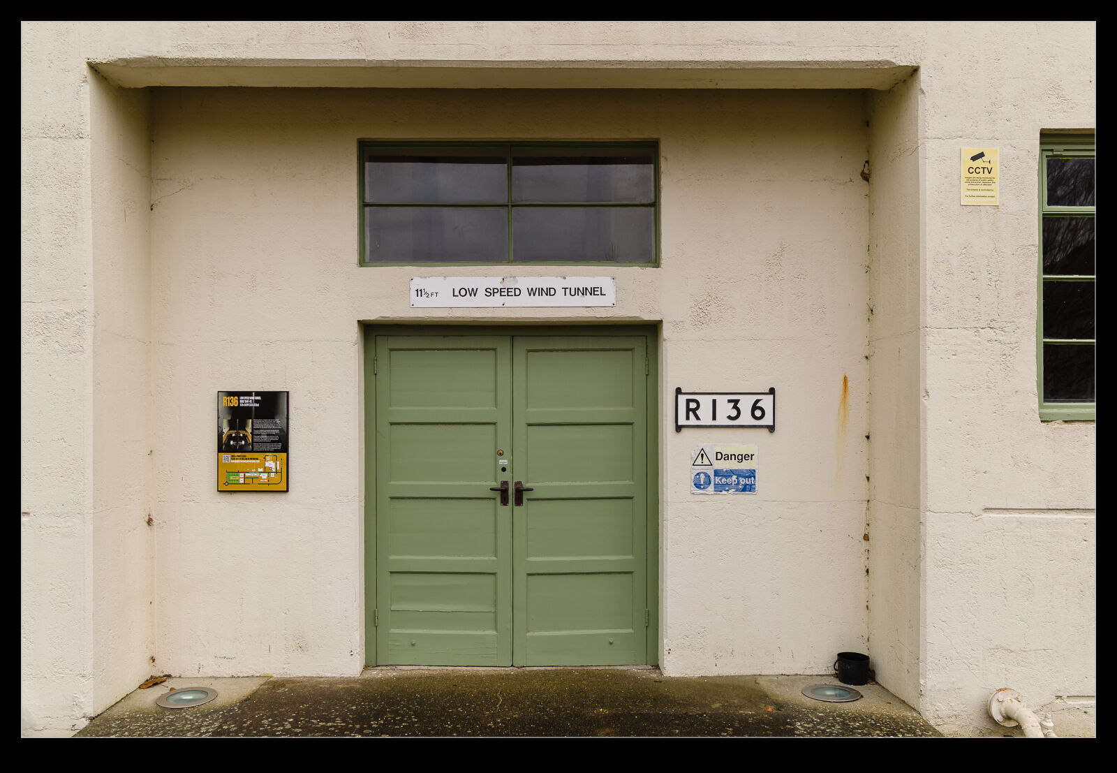
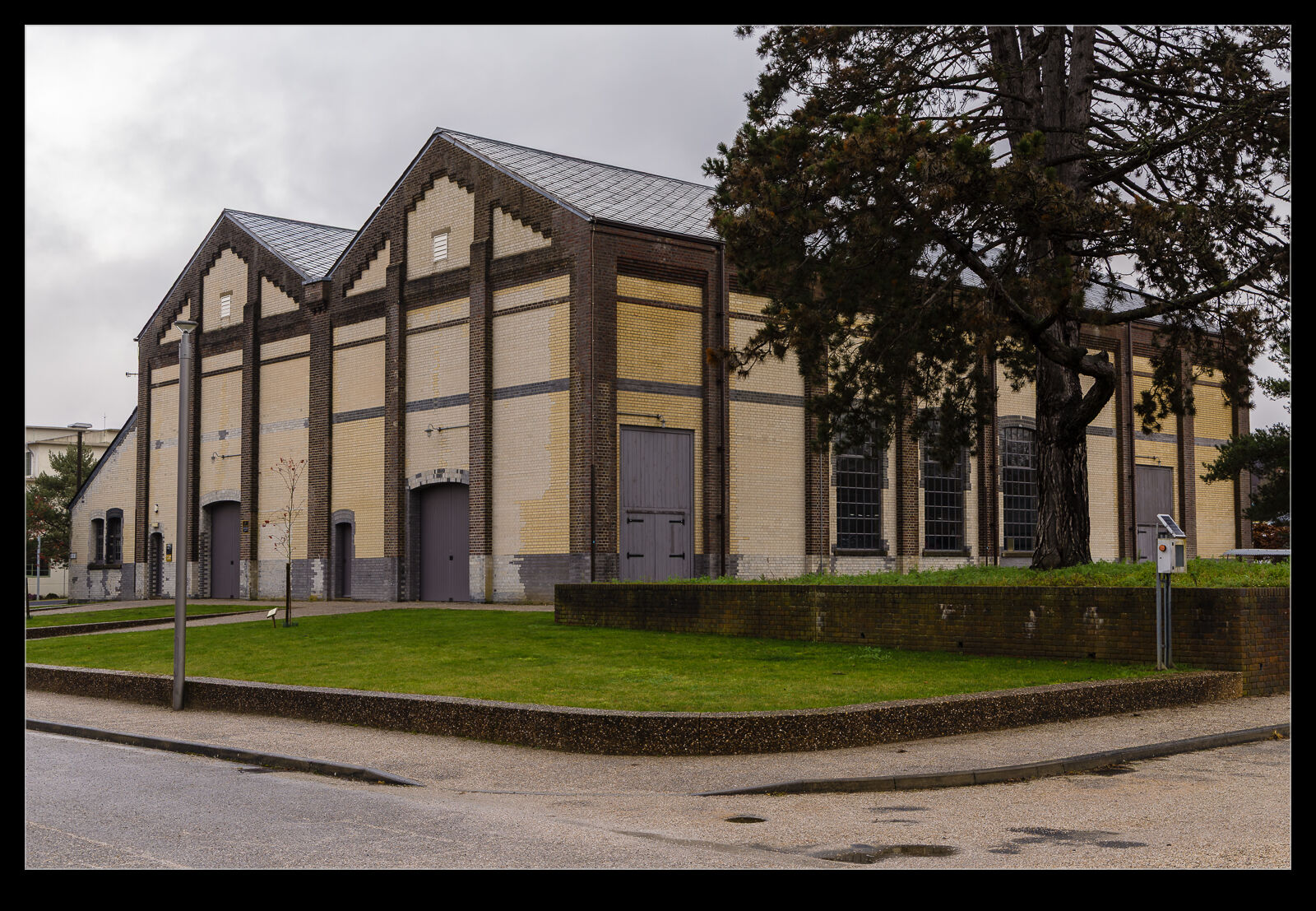
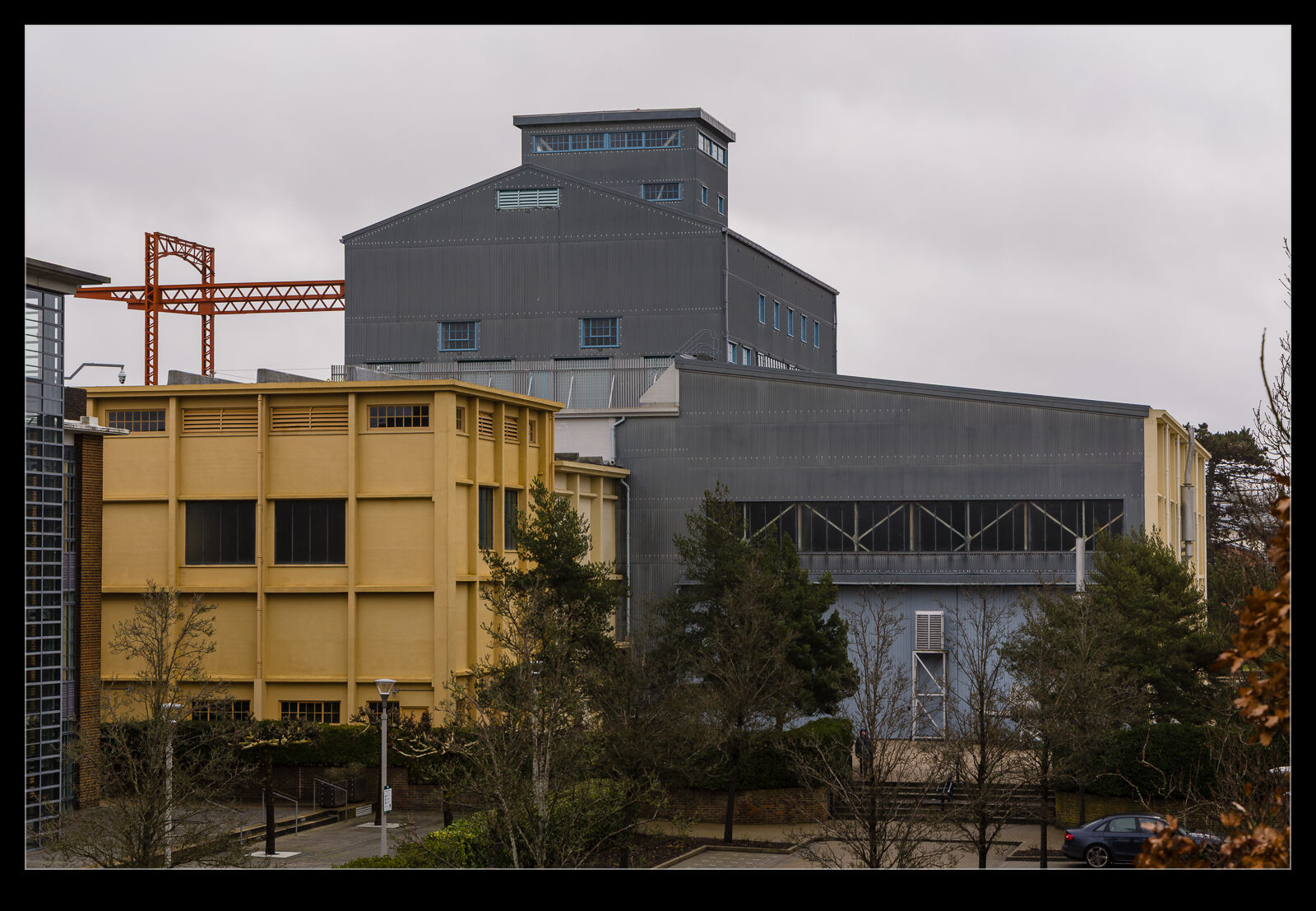
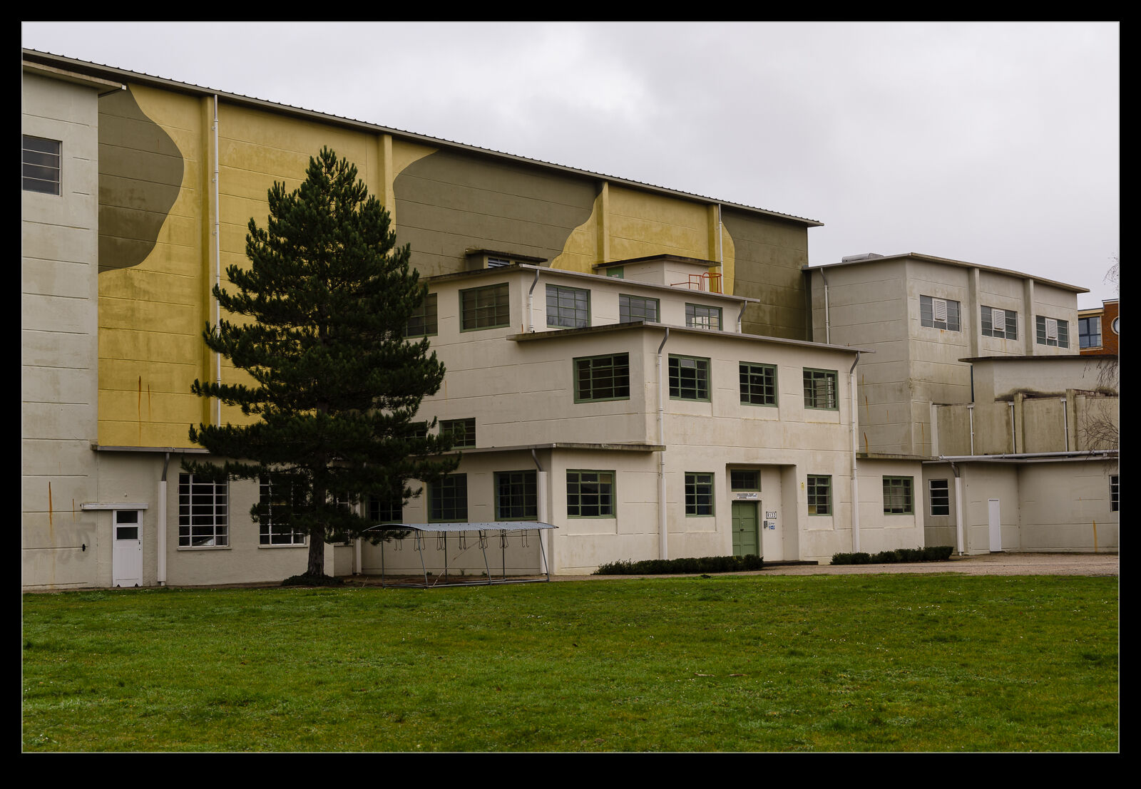
 There are some of the old facilities still there, though. A couple of wind tunnel buildings are in place – one of which has camouflage paint for some reason! There are plaques on the various buildings to give a bit of their history. I know of many test programmes that were undertaken in these facilities, and I believe they are still in use since some of the capabilities are still in high demand.
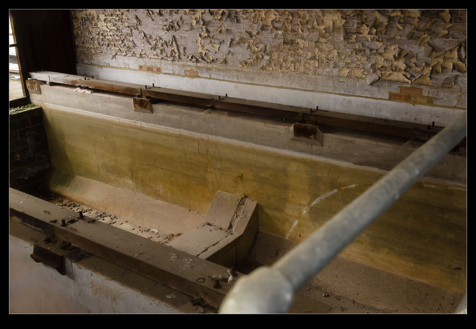
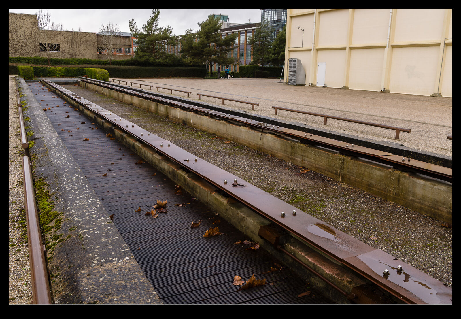
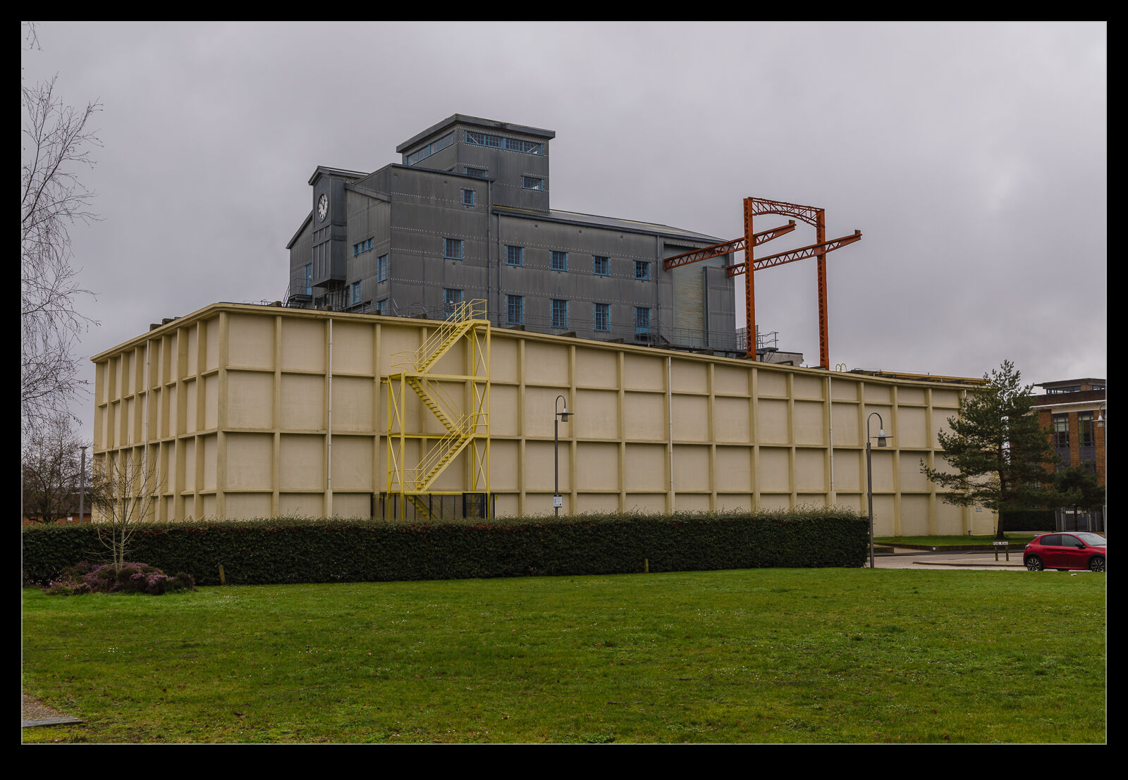
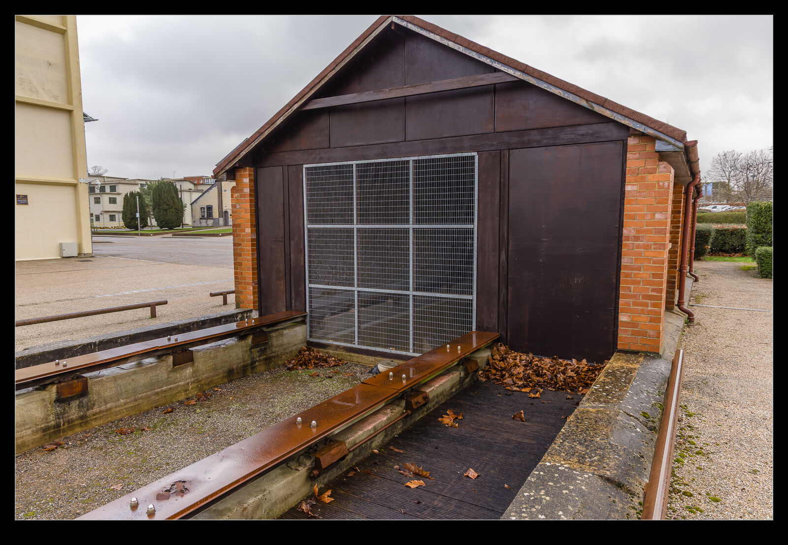
 One smaller building is the remains of a water test tank. This was apparently shortened at some point and now the building still has the tank profile inside while the outside has the test rails but seems to have been filled in. It is good that so much of the original facilities is still there even as redevelopment has taken place. Sadly, I won’t get to experience what it was like when it was at its busiest.