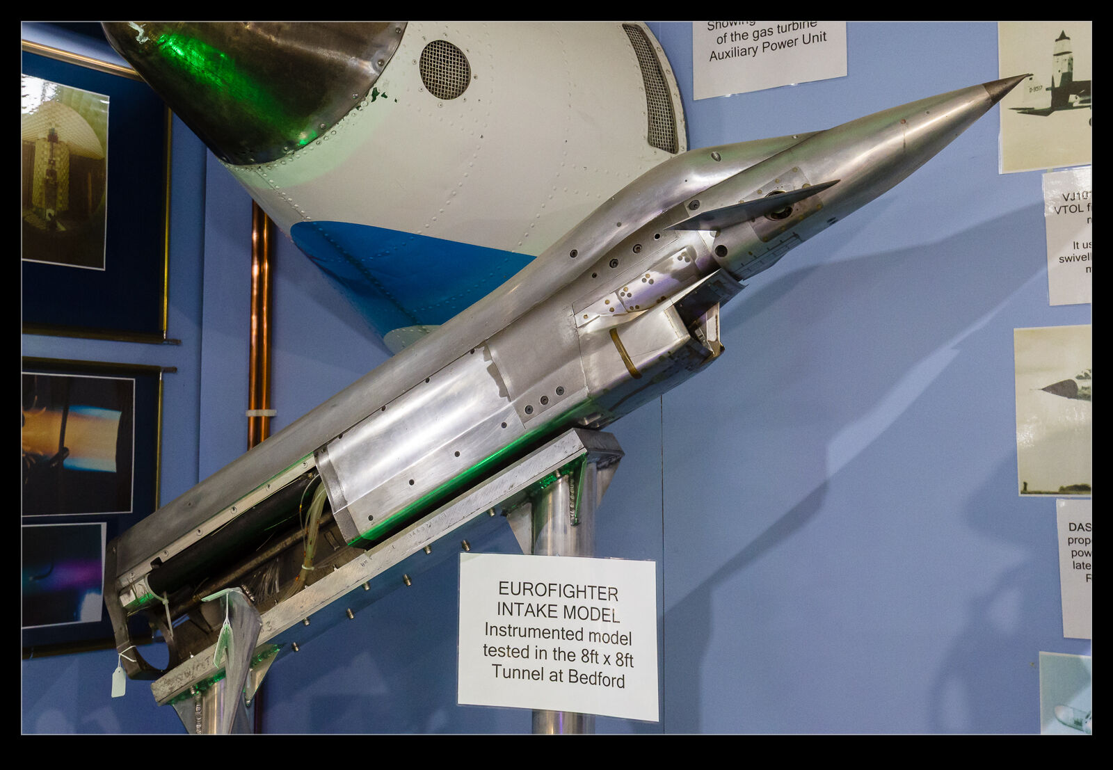
 The FAST museum at Farnborough has an extensive collection of wind tunnel models – both low and high speed. One that caught my eye was one that an old colleague of mine had worked on. It was a high-speed intake test model for what would become the Typhoon. You might be familiar with whole airframe wind tunnel models that are used to assess the aerodynamic characteristics of a plane. However, there are many different types of wind tunnel testing that get carried out. Intake testing is one of them.
This model served a number of purposes. There is the more obvious one which is assessing the quality of air coming down in the inlets as the aircraft changes angles of pitch and sideslip. A rake of probes will be set where the front of the engine would be located and then the test programme can assess how distorted the flow is as the aircraft manoeuvres. This is then compared to test data on what the engine can accept before it starts to have problems.
The Typhoon has the two engine inlets side by side. This can result in a problem with one engine affecting the other one. If an engine surges, a pressure wave will come back up in the inlet, and this can then affect the flow into the other engine. This surge interaction needed to be investigated prior to the plane flying.
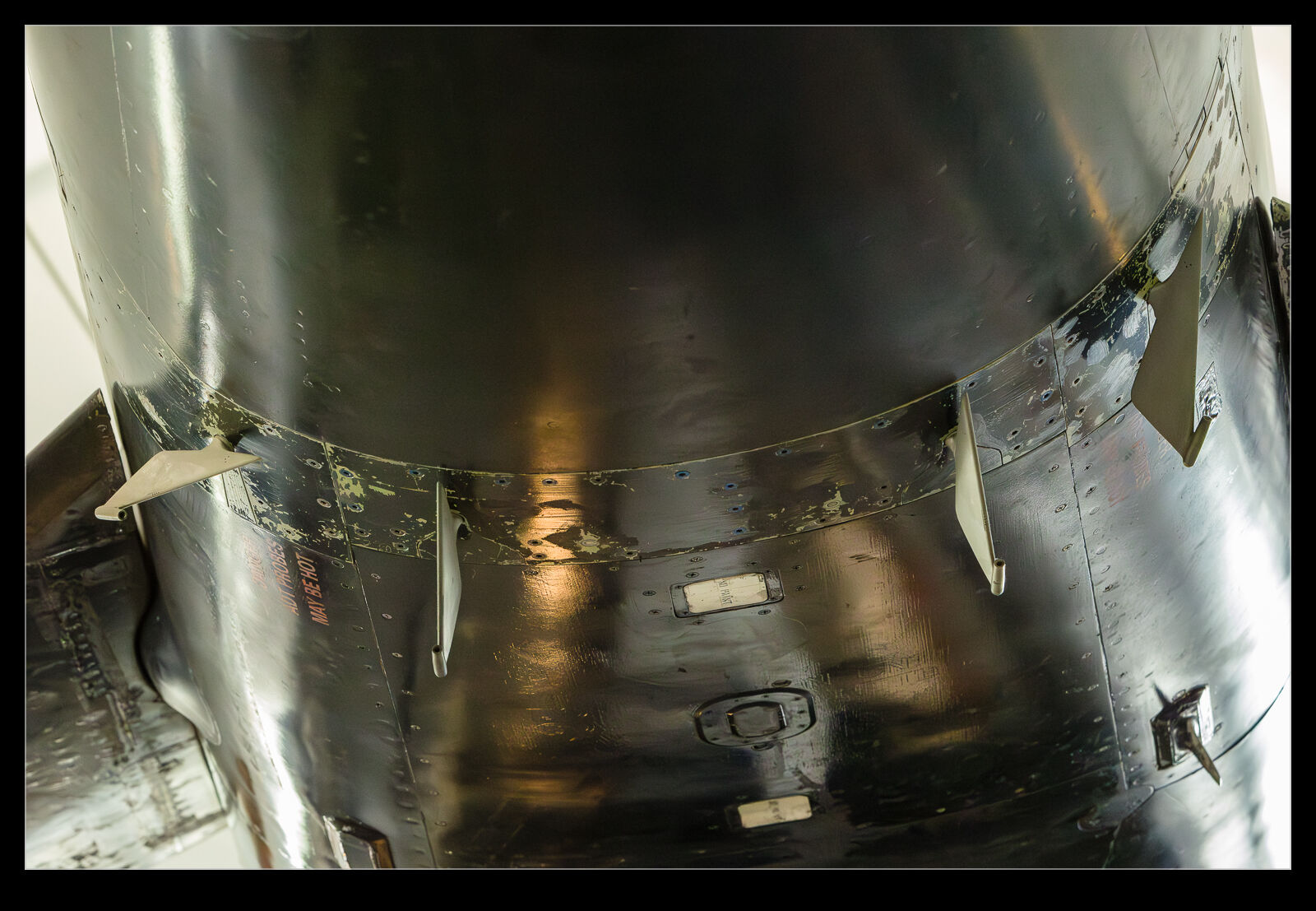 One less obvious test programme related to the testing of air data system inputs. Fly by wire aircraft are very dependent on the quality of the measurements of the aircraft’s pitch, roll and sideslip. As the aircraft changes its angles, the readings at the location of the probes need to be calibrated. Flight testing will refine this information, but you need to have initial data for the first flights before calibration can be demonstrated. The intake model is the one that was used to verify the flow field around these sensors. I’ve included a shot of the sensors on one of the development aircraft to show where they are.
This model was very important in the preparation of the Typhoon for flight test. Great to see the model has been preserved.